Informatie en richtlijnen voor een soepele workflow

Start
Pro
Voor een nog snellere workflow met IronCAD en Para-Flex is enige basisinformatie erg handig. Hieronder een lijst met richtlijnen die kunnen helpen bij het beheersen van de software en het versnellen van het volledige proces van ontwerp tot productie.
Het model in assemblages verdelen

Het gebruik van slimme panelen
Om automatische CNC-programmering en visuele weergave van materialen te kunnen gebruiken, wordt aanbevolen om onderdelen te gebruiken die zijn gemodelleerd met zogenaamde ‘Smart Panels’. These parts act like normal blocks in IronCAD, but have been expanded with additional intelligence. Dit voegt het bepalen van de dikte van een paneel toe, het herkennen van de onder- en bovenzijde en het toepassen van strepen en CNC-referentie op randen. De panelen die in de catalogi van Dynfos worden gebruikt, zijn opgebouwd uit slimme panelen.
Origin and labeling of edges
Elke 3D-vorm in IronCAD heeft een extrusierichting. Denk bij een paneel na over de basiscontour (vaak een rechthoekige vorm) die in een rechte richting wordt geëxtrudeerd om het materiaal met de juiste dikte te creëren. IronCAD geeft de extrusierichting aan met een blauwe pijl die begint bij een van de hoeken van de dwarsdoorsnede (of contour).
![]()
The exact position of the arrow doesn’t matter for the results of the CNC program, but its starting point indicates the origin (0, 0, 0) of the panel. Op basis van die oorsprong wordt de labeling van de randen (L1, L2, W1 en W2) gedaan. Wanneer het object wordt weergegeven zoals in de afbeelding hierboven en hieronder (extrusiepijl wijst naar beneden), wordt de rand rechts van de pijl aangeduid met L1. De rest van de randen is met de klok mee gelabeld, beginnend bij L1: W1, L2, en W2.
![]()
Standaard kasten
Materialen gebruikt uit catalogi geleverd door Dynfos standaard hebben L1 ingesteld als referentierand. Kasten uit een van deze catalogi zijn zo gemodelleerd dat rand L1 de voorkant van het paneel is. Standaard is deze zijde voorzien van kantenband en fungeert deze als CNC-referentie.
Toevoeging
– Para-Flex handles a maximum of 4 sides per panel, control of more sides will be added in the future. If this is desired at this moment, please contact us.
Extrude direction arrow
Zoals gezegd bepaalt de extrusiepijl de herkomst van onderdelen. De richting van deze aanwijzer heeft invloed op een aantal zaken, zoals het veranderen van de dikte en de onder- of bovenzijde van de plank.
Materiaaldikte
Als je de dikte van een paneel wijzigt door een nieuw materiaal te selecteren, blijft de oorsprong op dezelfde positie. Gegeven dit feit zal de paneeldikte op voorspelbare wijze toenemen of afnemen.
Boven- of onderkant van paneel
De richting van de extrusiepijl bepaalt de boven- of onderkant van een paneel, wat relevant kan zijn voor CNC-bewerkingen. Wanneer een paneel alleen wordt geprofileerd, wijst de pijl naar de onderkant van het paneel, ook wel het machinebed, omdat de bovenkant van het paneel naar de snijkop wijst.
Bij het bewerken van een paneel waarvan beide zijden boorvormen bevatten, wordt standaard de zijde met de meeste boorvormen als bovenzijde behandeld en als eerste bewerkt.
Standard cabinets
When changing the material thickness of a standard cabinet, panels will increase towards the outside of the model, because in these models the extrusion arrow is directed outside. This way internal items, like shelf supports or drawers, will stay at the right position, connected to the side panels. Met behulp van het rektool is de kast eenvoudig op de gewenste afmetingen af te stellen.
Drawing contours
In order to get files as desired for processing on a CNC machine, a number of guidelines will have to be taken into account.
Using Chamfer/Blends instead of Cross section editing
Chamfers, cutouts and blends can be drawn using different methods. Though, every method can lead to different programs for CNC machining.
Editing the cross section of a panel gives a lot of freedom, but be aware that when resizing or stretching parts the lines in the cross section are scaled, when no constraints are used.
Also the recognition and visualization of the standard edges (L1, W1, L2, W2) and the CNC reference edge, can be disturbed when new lines are added to the cross section of a panel. To get around that, it is best to use Chamfer or Blend features, which also eliminates the problem of aspect ratio locks between the length and width of a shape.
See the tip below for using Contour Handles for faster editing shapes.
Contours in the Cross-sections of shapes
A contour completely shaped in the Cross Section of a panel will be exported to a CNC program exactly like drawn. Keep in mind that drawing both the outer contour as the inner contour (including drills) in one cross section can’t be handled by the CAM module. For example the outer contour should be drawn in the Cross Section of the panel, and the inner contour, cut out or drills should be drawn in the cross section of another IntelliShape like a Cut Extrude.
Drawing curved lines
Curved lines in the Cross Section of a shape have to be drawn as arcs, to be processed well to the CNC program. Since the CAD module doesn’t recognize Spline, Bezier, and Elipse curves, these lines have to be drawn in (or converted to) arcs before exporting to CNC.
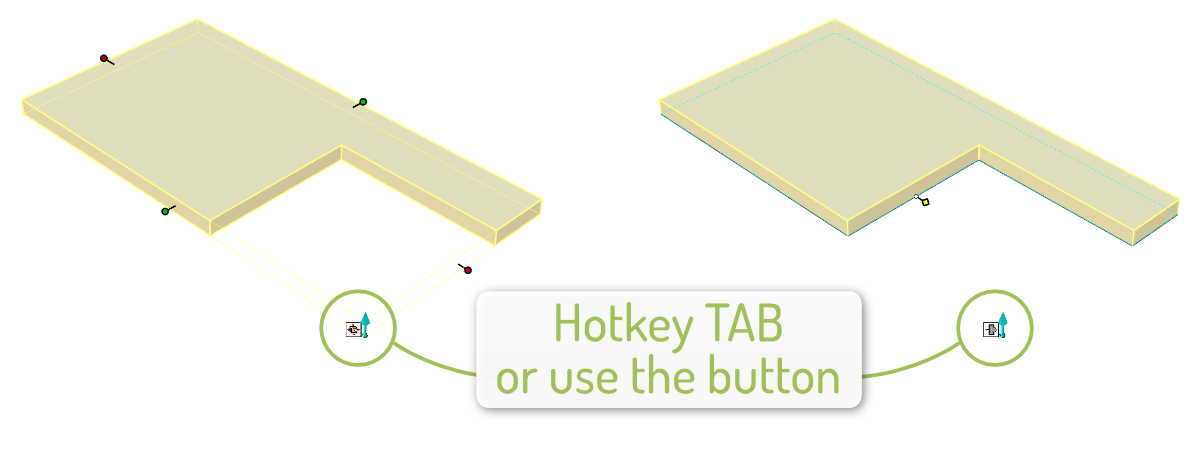
tip: Switch type of Edit handles
The handles of an IntelliShape normally are set to so called Sizebox handles. This method resizes the complete shape without taking into account the aspect ratio of the shape. Certain elements in the Cross Section are lockable by applying constraints, but often a faster method is switching to Contour handles. Using Contour Handles the Cross Section of a shape can be edited directly on the edges, without affecting other parts of the shape. When having an IntelliShape selected, hotkey TAB can be used to switch between the handle methods.
Rabbet joints and cutouts
Rabbet joints and cut outs can be drawn as desired in IronCAD, the drawn shapes will be sent to the CNC program. To create clean rabbet cuts it is useful to draw the cut out shape slightly bigger than the edges of the panel, for example using the offset function in the Cross Section of the shape.
Tip: Parts in BOM
Parts with ‘Include this shape in BOM’ switched off in their IronCAD properties, will be excluded from the Para-Flex part list. It is usable for cleaning up your working list, like elements of the environment in the design that shouldn’t be shown in Para-Flex. After switching off ‘Include this shape in BOM’ the parts still can be included in the output lists, for instance Cutting, CNC and Purchase, depending on the parts applied processes.