
Assigning materials to selected parts
![]() Start
Start ![]() Pro
Pro
Description
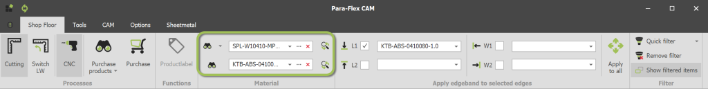
The Material section on the Shop Floor ribbon bar contains several items. Starting with the button Browse Material Database ![]() , followed by a material list and on the right side the button Replace Material
, followed by a material list and on the right side the button Replace Material ![]() . A material can only be added to a part when a process like Cutting or CNC is assigned to it.
. A material can only be added to a part when a process like Cutting or CNC is assigned to it.
The top row of material settings applies to base materials (panels, profiles), while the bottom row applies to edgebanding.
Quickly navigate to: Material Editor – Panels or Material Editor – Edgeband
Browse the database if necessary
If necessary, first add the desired material from the database to the materials list. Click the “Browse” button ![]() and double-click the desired material in the window that appears. For more information, visit the previous page about searching the databases.
and double-click the desired material in the window that appears. For more information, visit the previous page about searching the databases.
Material list
The material list shows all the materials assigned to parts in the current model. It can be opened by clicking on the material name or using the small arrow ![]() next to it. The second button on the list
next to it. The second button on the list ![]() opens the Material Editor, see information below. The last button
opens the Material Editor, see information below. The last button ![]() removes the material from the Material List (belonging to the current model), no changes are made to Material Database (for general use).
removes the material from the Material List (belonging to the current model), no changes are made to Material Database (for general use).
Applying materials
The material selected from the material list will be applied to a selected part when switching on Cutting or CNC. If a part already has material allocation, make sure to deactivate the processes Cutting and CNC so the new material can be applied using these buttons.
Users of Para-Flex Pro/CAM can switch on Automatically select new material in the Para-Flex Settings, that way a newly selected material from the list is instantly applied to the selected part(s), regardless of whether processes have been applied to a part or not.
The search bar at the top of the opened material list can be used to filter the results, in order to find the material to be applied more easy.

Material Editor – Panels
The Material editor is used to create or edit materials in the current model or the general database. All information belonging to the material can be added (or overwritten) in the corresponding fields.

Adding or editing panel materials
Code
To edit an existing material, do not change the Code field, only edit other properties (except for the thickness, see Conditions below). When ready, click Apply to save the changes.
To create a new material start by simply editing the existing code in the top field. As desired, the material properties can be changed and available board sizes can be added. Click Apply to save the changes into a new material.
The characters and their position within the code are important as it can drive machines, so work carefully when adding new materials to the model or database.
The default material database in Para-flex is build up starting with three characters describing the kind of material, and ending with the board thickness. This is recommended to ease automation of driving production machines. Between this information text can be added like the decor code and name of the supplier.
Description
This field will not be used for automation processes so it can completely contain the information desired by the user. A useful field for identifying the material.
Thickness
Specify the thickness of the material. Users of Para-Flex Pro have the availability to drive the thickness of a panel in the 3D model by this value. So when switching to a different material thickness, this change is instantly vissible in the IronCAD model (Size box value ‘H’).
Grain
When a material or decor contains a grain direction this can be set to AlongLength. The Optimizer will place panels in a board, regarding the right direction. Set this value to None for uniform decors so the Optimizer can get a more efficient result by rotating panels by 90° if needed. See Conditions below for more information on adding ‘Short grain’ boards.
Color and Texture file
A color and, if applicable, a texture can be assigned to the material to get a quick indication of the looks. Para-Flex Pro-users have the availability to see this color or texture appearing instantly on the part in the 3D model.
Apply & Update external Database
Clicking Apply saves the new or edited material to the local database, which is saved in the current file of the 3D model.
When checking Update external Database, the material is also stored in the used general database, so it can be used in other designs or by colleagues.
Automatic material naming
When this box is checked, the board name (as seen in the Material dimension dialog and in the database) is automatically updated. This way the contents of the Code field is automatically transefered to the Board name, in order to reduce mistakes.
The available board sizes of the corresponding material can be entered in the Material dimension Dialog. Click on the three dots (…) on the right of the field showing (Collection). The available board sizes will be used by the Optimization engine to calculate the need of material.

Adding or editing Material dimensions
Add & Remove
Each material should always have at least one board size available . Use the Add and Remove buttons to create a complete list of board sizes available. The Add-button adds the set board size to the material, from that point the Optimizer can calculate the materials needed. At least one board size must be added in order to create a material.
Move Up/Down & Search
A panel size can be moved up and down in the list by the buttons Move Up or Move Down.
Search will pop up a search field on top of the items list. After entering the desired text, use the Enter key to start searching.
Length & Width
The available board sizes of the corresponding material can be entered in the appropriate fields. For materials with grain direction, use the Length field to correspond with this orientation. Also see Note 1 below.
Material dimension name
This field, also called Board Name in the default database, should combine Material Code and Board size. This information can be used for feeding programs for Enterprise Resource Planning (ERP). When Automatic material naming is switched on, the first part of this field is updated corresponding to the Material Code. Selecting this field instantly updates the size part of the name, according to the Width and Length values
Quantity
The Quantity field is to be used to drive the optimization process to calculate with the right number of available boards. When different board sizes are on stock, the panel that can be used most efficiently is chosen first by the Optimization program.
Material cost
Price of a m2 of the selected board, for example to be used by the optimisation engine.
Thickness
This value can’t be changed here, but has to be set by the Thickness field in the Material Editor.
Note 1
Materials containing grain direction are (by default) only supported with the direction of the grain along the Length value of the board (so called ‘long grain’). For materials with a grain direction along the short side of the board (so called ‘short grain’), simply create a material and switch the length and width values. So entering the length value of the short side, in the Length field, and the length of the long side in the Width field.
Tip
Within Options > Settings > Para-Flex a value for fixed over dimensions can be set. This value will be applied to all parts with material that meets the criteria of the corresponding minimum sizes (length, width and surface). Useful when working withe rough/gross sizes that need to be cut clean afterwards.
Material Editor – Edgeband
The Material editor for Edgeband is used to create or edit edgeband materials in the current model or the general database. All information belonging to the material can be added (or overwritten) in the corresponding fields.
Pay extra attention to the use of the Thickness field, as this can affect the panel dimensions sent to the cutting lists.

Adding or editing Edgeband materials
Code
To edit an existing edgeband material, do not change the Code field, only edit other properties. When ready, click Apply to save the changes to the current material.
To create a new edgeband material start by simply editing the existing code in the top field. As desired, the material properties can be changed. Click Apply to save the changes into a new material.
Compared to the material code of panels, the code of edgeband material is not used for driving machines. This gives a lot of freedom to create a customized code. Nevertheless, it is useful to use a standard formula to easily recognize the specifications of edging material.
Description
Use this field to enter information about the corresponding decor of the panel.
Thickness
The Thickness field may contains the physical thickness of the edgeband, that will be automatically reduced relative to the net size. The net sizes are based on the size box values of the IntelliShapes in IronCAD.
If the thickness of the edgeband is not to be taken into account on the exported panel sizes, please leave this field set to zero. This is often the case, because a pre-milling cutter is used before applying edgebanding.
If a pre-milling cutter is not in use and working with gross dimensions is desired, filling the correct edgeband thinkness in this field is useful.
Note that columns containing gross values can be shown in the Data Grid and also been used in reports or exported CSV files. See also Core Trim below to compensate edgeband thickness if needed.
Core Trim
The Core Trim field provides a “plus” on net dimensions of a panel, related to the specified edge. As the thickness value of the edgeband material can be used for having the right gross dimensions, Core Trim can be used for compensation.
Some examples
Core trim set to 0: No compensation on the gross size (net panel size minus edgeband material thickness).
Core Trim set to -2: For edge material with a thickness set to 2mm, this thickness is fully compensated. Useful when a pre-mill on an edgebander removes the thickness of the edgeband material from the panel, so that the gross cutting dimensions remain the same as net.
Core trim at +5: The panel is cut larger than the net size, in order to cut it clean afterwards (for example, after veneering the panel).
Core trim at +10mm or +20mm: Useful to have cutting space for a 45° miter for example.
Color and Texture file
A color and, if applicable a texture, can be assigned to the edgeband material to get a quick indication of the looks. Para-Flex Pro-users have the availability to see this color or texture appearing instantly on the part in the 3D model. In the Options menu the the visualization of the edgeband can be set to use the specified color in the database or use the same color of the decor of the panel. Depending of the used ERP program it’s sometimes better to set this to this last mentioned option.
Apply & Update external Database
Clicking Apply saves the new or edited material to the local database, which is saved in the current file of the 3D model.
When checking Update external Database, the material is also stored in the used general database, so it can be used in other designs or by colleagues.
Note 2
Note that changes to material and edgebanding will not be processed if the material is already in use in the model. Therefore, apply an alternative material to the panel(s) first and click Import Materials (on the Tools tab) to clean up the material list. Then modify the panel or edgebanding material and re-link this material to the desired parts. These steps are necessary in order that the materials are stored in the document, as long as they are in use in this document, they cannot be changed and thus adjustments are not processed.
Tip
A fixed overlength for an edgebander can be set in Options > Settings > Optimize. The value set at the Edgeband Fixed Overlength field will added to the calculation of each edge, resulting in an even more realistic requirement.
Conditions
– A material can only be added to a part when the process of Cutting or CNC is assigned to it.
– At least one board size has to be added to a new material before it can be saved.
– The thickness value of an existing panel material can’t be changed. If necessary, edit the existing name and thickness to create a new material.


