Apply CAM tooling to IntelliShapes
![]() CAM
CAM
Description
Opens a window which is used to apply CAM tooling tags to selected IntelliShapes. First select a part to be able to use this button.
CAD Tools are used to override the standard ruleset in the milling program. They can be applied directly in IronCAD. For example, a recessed hole is normally fully machined out, but this is not always necessary. In case of the flanged edge of a sink, it is not required to fully chip this shape because a through-and-through cutout is also milled into the worktop to accommodate the sink. In such a case, CAD Tool CONTOUR could be linked to the IntelliShape cutting out the flange edge to save milling time.
A CAD tool can also be added to HWDrill Shapes so that it is automatically applied to the holes created. Since cut outs created using the Drill function take on the name of the drill shape, the tool is applied each time drilling is performed.
Other available tools are shown below, including clear images and a 3D sample file to be opened in IronCAD.
To apply CAD Tools to IntelliShapes, the fastest way is to type them in. See below for more information.

Apply tools
Applies selected CAD tool to selected intellishape(s)
Delete all
Deletes all applied CAD tools
Delete selected item(s)
Deletes CAD tool from selected intellishape(s)
Available CAD Tools
Most of the CAM operations are covered with default CAD tools we supply to our CAM users. See below for examples and check the impressions to clearly understand the working.
|DELETERemove this operation from the CNC program. |
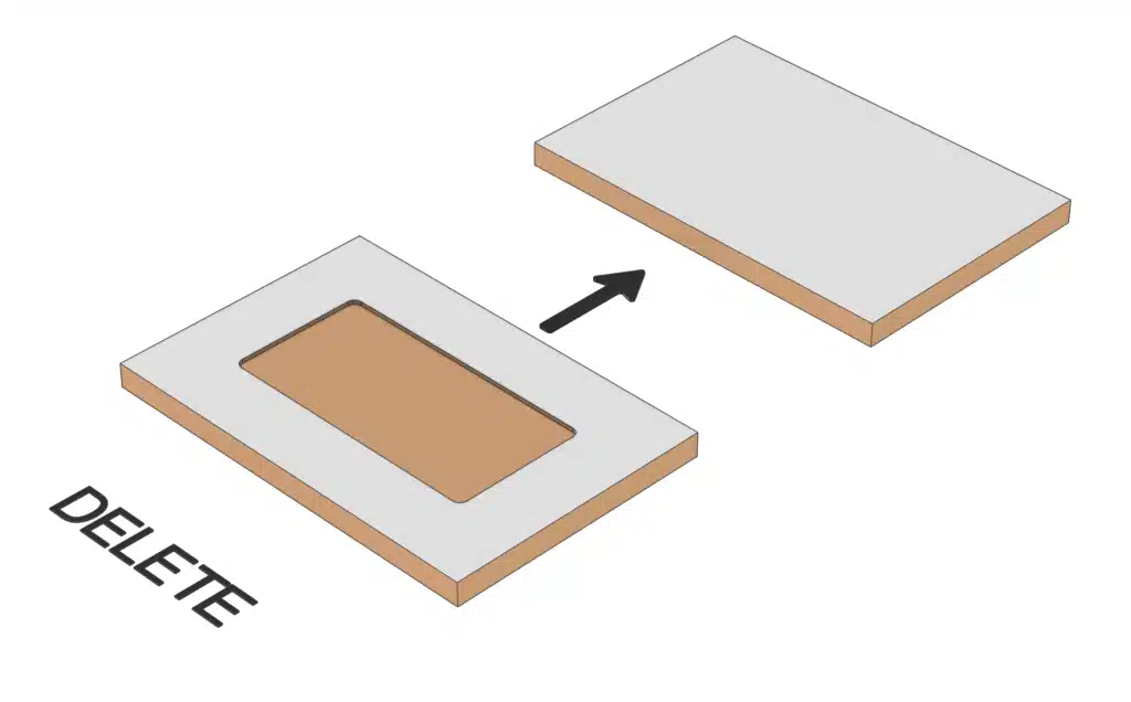 |
|HORBLADEApply a horizontal sawing blade to an (rectangular shaped) H-Block on the end sides of a board instead of using a drill. |
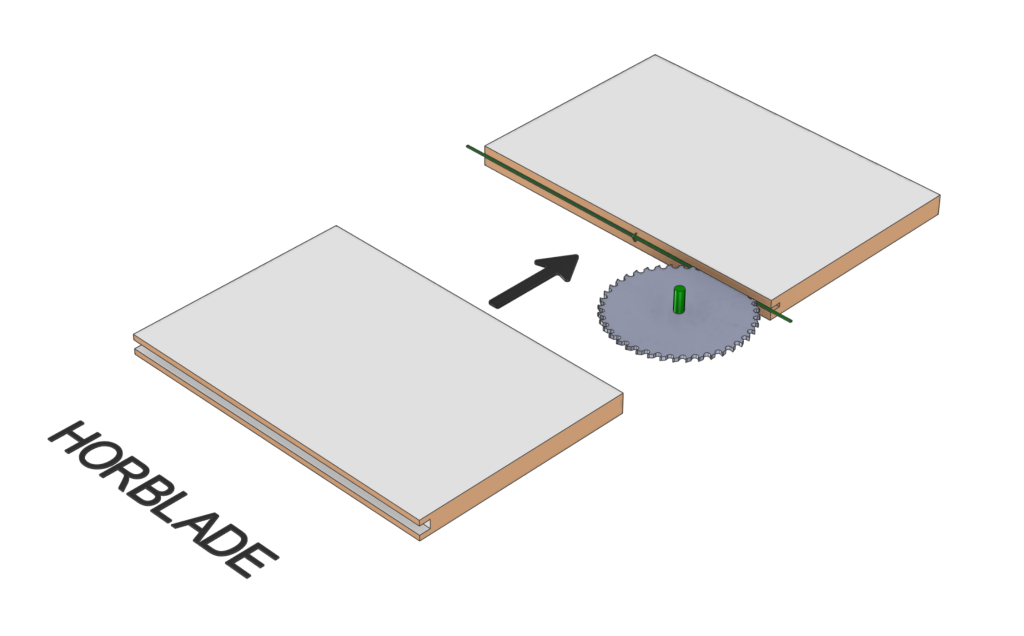 |
|VERBLADEApply a vertical sawing blade to an (rectangular shaped) H-Block instead of using a drill. |
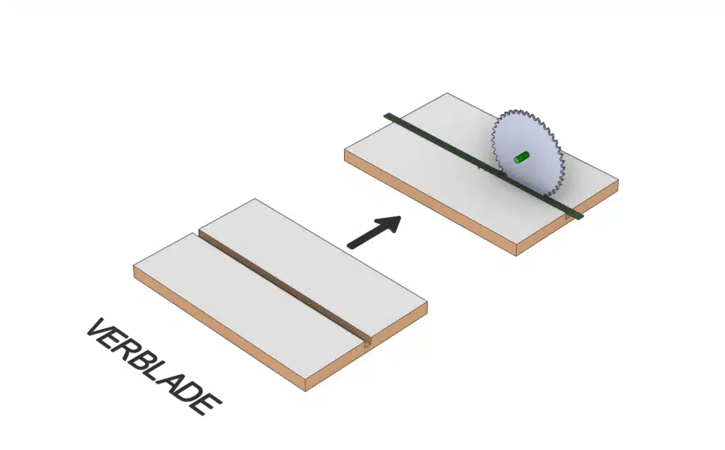 |
|NESTOften used in combination with a nesting phase in the CAM software. This tool combines the outer contour with the selected cutout shape. |
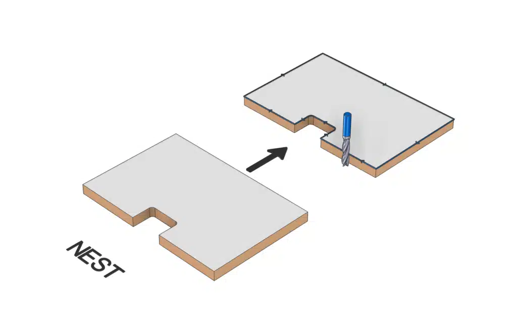 |
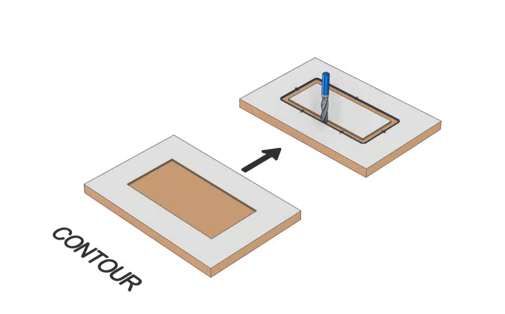
|CONTOURSet an H-Block to be contoured instead of completely removing the inside material. |
 |
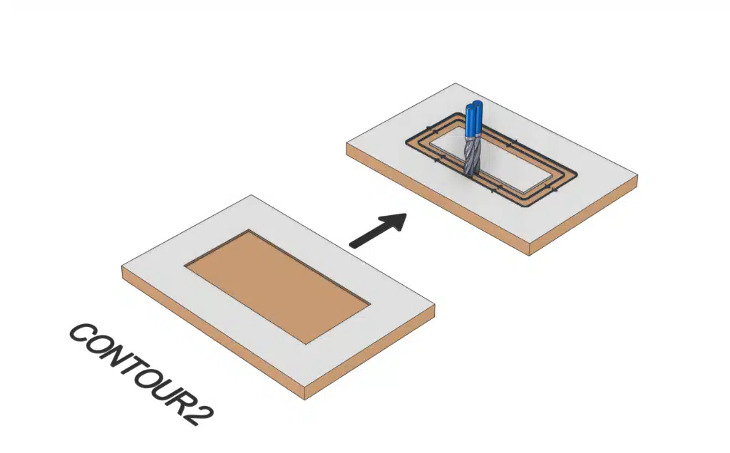
|CONTOUR2 or |OFFSETSame as |CONTOUR, but adds an extra inward milling line. |
 |
|CONTOUR3 or |OFFSET2Same as |CONTOUR, but adds two inward milling lines. |
 |
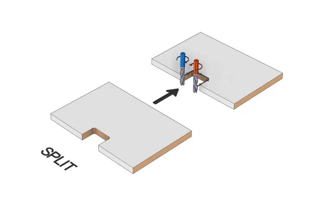
|SPLITSplits the H-Block into two parts to prevent edgebanding from breaking when machining near panel edges. |
 |
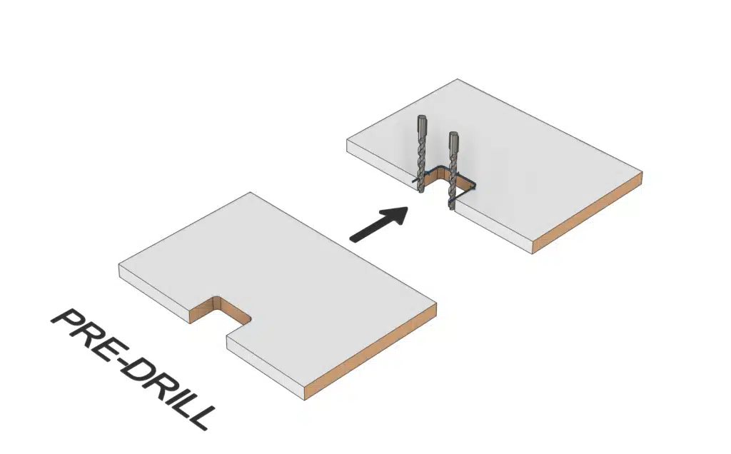
|PREDRILLApply pre-drilling to the start and end points of a milling contour. |
 |
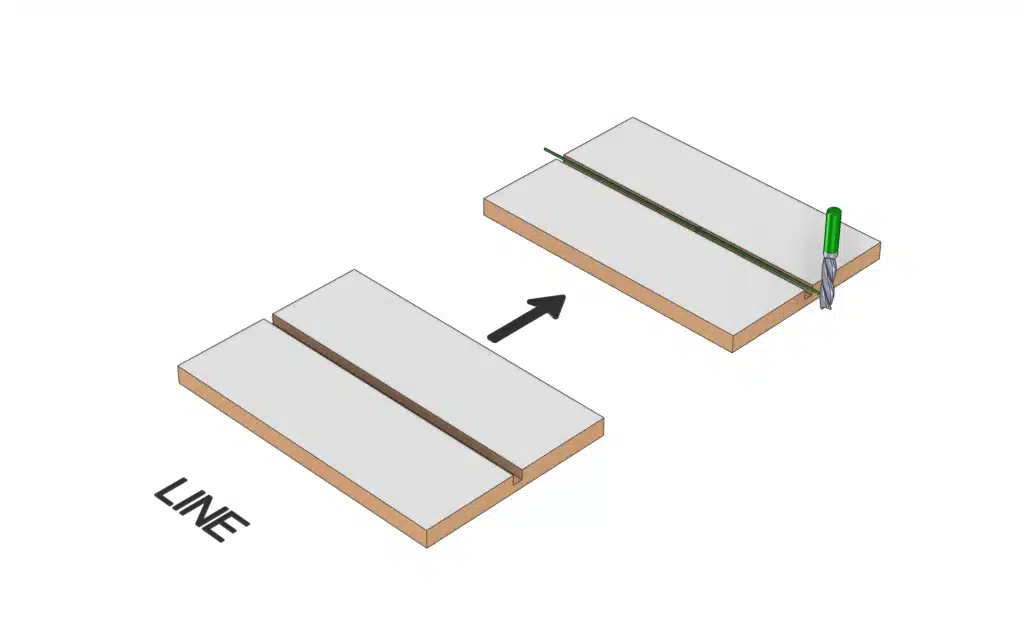
|LINETreat a rectangular H-block as a line operation over its center line. |
 |
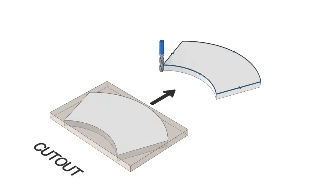
|CUTOUTTreat an H-block as an outer contour, so the panel first can be cutted using oversized dimensions. |
 |
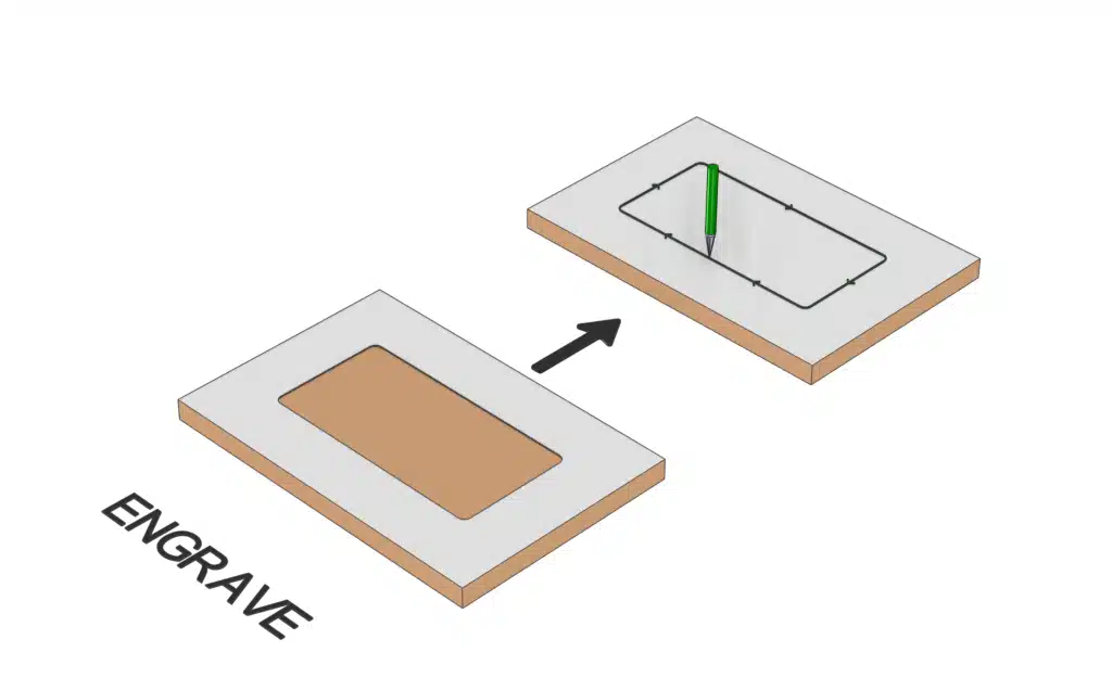
|ENGRAVEUse the engraving tool along the outline of the H-block. |
 |
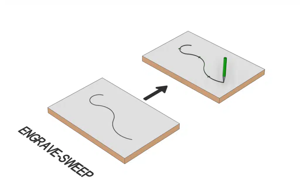
|ENGRAVE-SWEEPUse the engraving tool along the center line of a sweep shape. |
 |
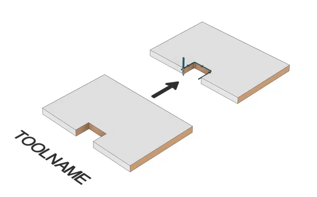
|TOOLNAMEApply a specific drilling or milling tool to a contour of an H-Block. |
 |
Applying custom tooling by typing
Use the macro’s shown below in order to apply CAM Tooling in a fast way. Simply type a vertical line “|” followed by the desired (CAM Tool) text in the name field of an IntelliShape.
Example:
Example of CAD Tools applied to a dowel:

Download the IronCAD file containing the samples shown above here. (Suitable for IC2026 and higher)
Conditions
- This functionality is only available for users of Para-Flex CAM
- The button CAM Tooling is only active when a part is selected
Tip
To rename items in IronCAD (for example, in the catalogs and the Scene Browser), first select an item and then click on it again.