Apply a pre-defined pattern from the list
![]() Start
Start ![]() Pro
Pro
Description
Applies a preset formula to a selected linear pattern. Information about how to use Smart Patterns and the possibilities with formulas can be found below.
Conditions
- Keep in mind that the smart pattern refers to the L-, W- of H-value of an IntelliShape, by its formula. The direction of the selected pattern has to point in the corresponding axis to work properly.
Ready-to-use patterns
Click here to open the complete file with all smart patterns. Handy to quickly test and adjust examples.
Smart patterns explained
In many designs patterns are used to automate positioning objects. For example system holes for shelfs in furniture or repeating cams on an axle. Using a pattern results in multiple objects, simply based on two values: quantity and distance, both specified by the user.
When using Para-Flex in IronCAD, the values that drive the pattern can be extracted from the name of the pattern. This technique is used to quickly update items, like the distribution of hinges when the height of a cabinet is changed.
Most of the example data that comes with Para-Flex uses so called Smart Patterns to quickly recalculate quantity and position of many objects. For example to position hinges, adding system holes and create extra adjustable legs when needed.
How to create a pattern using the Triball
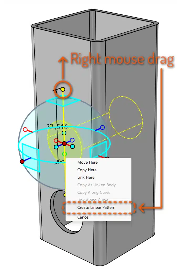
For creating a basic pattern in IronCAD, often the Triball is used:
 Select the item you want to use in a driven pattern.
- Activate the Triball (hotkey ‘Q’).
- Use a right mouse drag on one of the outer handles in the direction the pattern has to be created.
- Choose ‘Create Linear Pattern’
- Enter the values as desired or, even better, simply click OK and let the values be driven by the name of the pattern, see below.
 Select the item you want to use in a driven pattern.
How to convert Patterns into Smart Patterns
As mentioned the values to be used creating the pattern are extracted from the patterns name. This name starts with an underscore ‘_’ and a link to a property of the base object, like the height of a front panel (in this case ‘_L’). This property can refer to every sizebox value of the panel, so length ‘_L’, width ‘_W’ or height ‘_H’. Usually the property corresponds to the direction of the pattern.
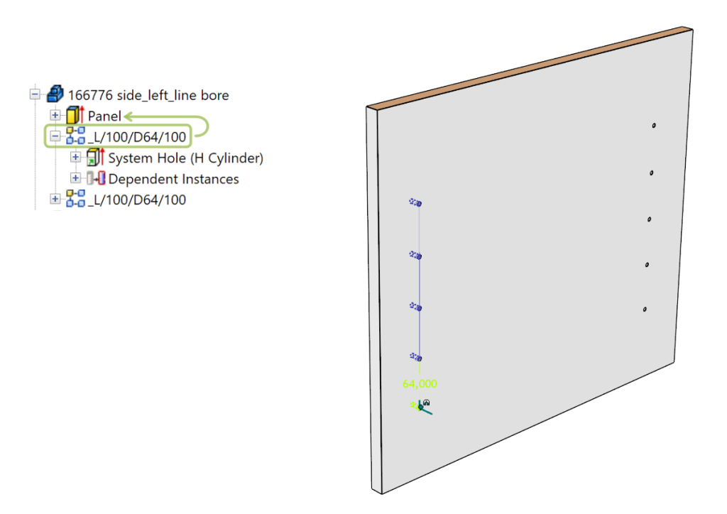
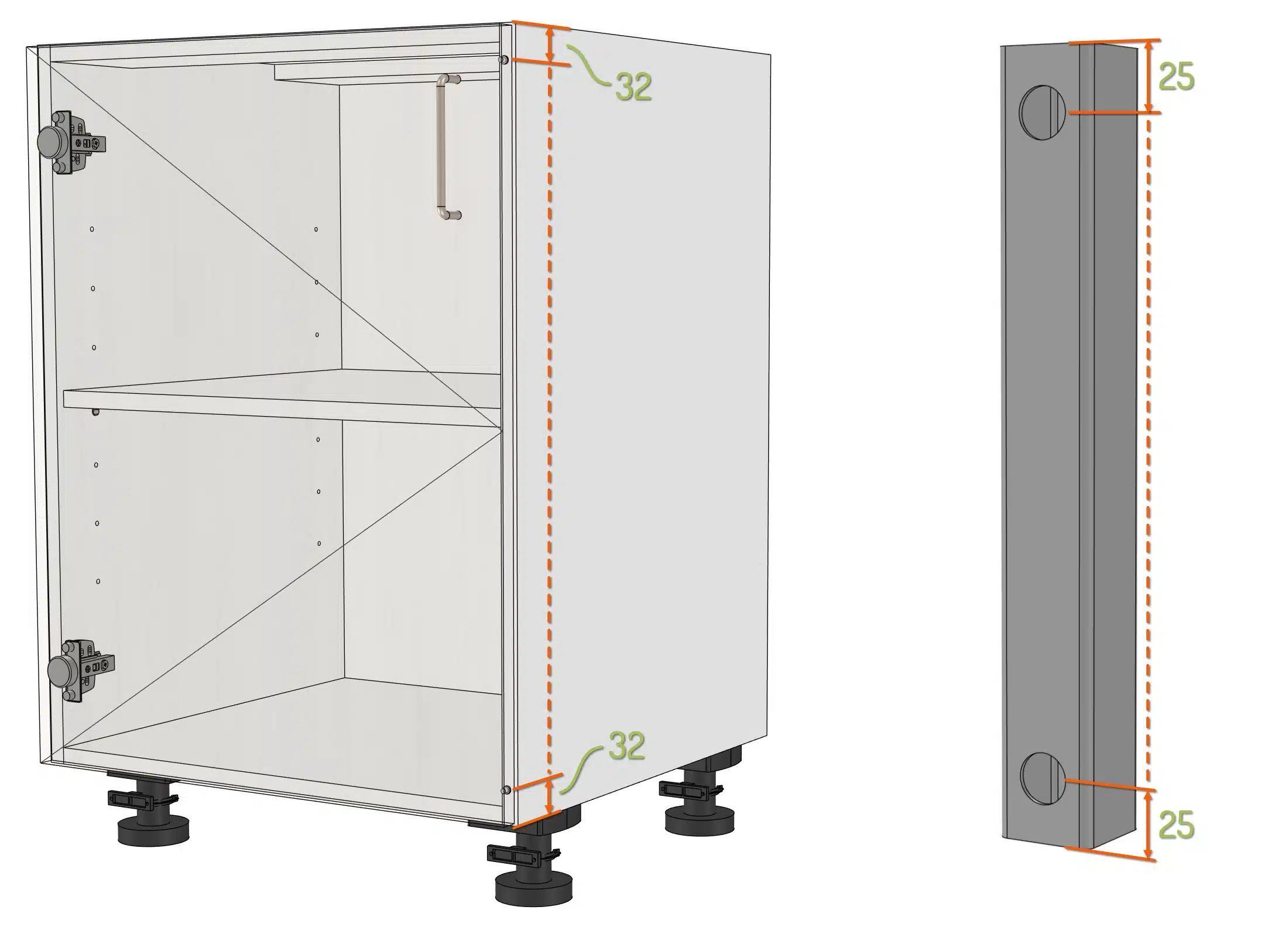
To clarify this, see this example of system holes in the side panel of a cabinet. It will show more variables that are explained below.
The name of the used pattern is: _L/100/64/100
Looking at the pattern step by step will show 4 parameters, divided by a slash ‘/’:

Summarizing the four parameters to enter are:
- Direction value (to extract the correct length for calculation)
- Starting distance
- Minimum center distance between objects
- End distance
Linking to the base object
As mentioned the first parameter of a pattern name refers to the object hierarchically above the object in the pattern. This can be an IntelliShape in the same part, or another part in the same assembly, see examples below.
Pattern within one part
System holes in a side panel exist within one part, including the panel (an IntelliShape) and the hole(s) (also an IntelliShape). Using _L at the beginning of the name lets the pattern refer to the L-value of the shape ‘above’ the hole, so that’s the IntelliShape called Panel.
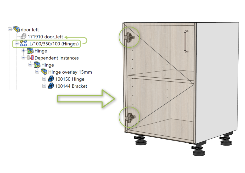
Pattern within an assembly
Since hinges are separate parts, using them in a Smart Pattern the first parameter refers to another part, often the door panel. For example the position (and quantity) of the hinges is linked to the height of the door panel an both parts are grouped in an assembly. The object to refer to must be hierarchically above the position of the pattern and on top of the list in the assembly. Note that the assembly may contain other parts, like a door handle and buffers.
Tip
To divide the parameters of the pattern a slash / but also a backslash \ can be used. Choose between the two options, using both within one name is not allowed.
Types and details of Smart patterns
There are multiple types of Smart Patterns that can be used, each for specific situations in product and furniture design. The user is always in control of the center distance and quantity of items, but can also switch specific first or last items on or off.
( <, > or =) Control the center distance by symbols
The center distance, or so called system distance between objects is used for calculating the quantity of hinges and their position.
The type of distance can be controlled by the mathematical symbols <, > and =. For example:
The preferred type of center distance to be used when no mathematical symbol is added to the value can be set in the Settings menu (on the Options ribbon bar). Look for Default Smart Pattern operator and adjust it as required (by default “<“).
When using a fixed distance (symbol =), the end distance of the pattern will be variable and will become a distance between the minimum of the given end distance and the given fixed distance. According to the mentioned sample above the distance of the last hinge to the end of the front panel will be between 350mm and 260mm (350-90).
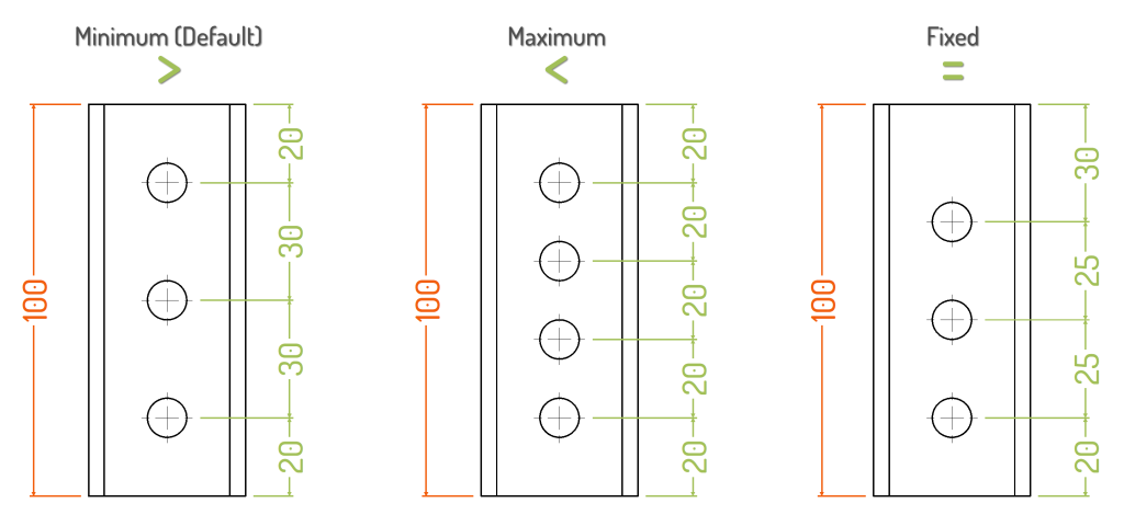
Below three examples of the difference in result when using the center distance with a specific symbol.
- Left: _H/20/>25/20 (Or simply _H/20/25/20 when “> ” is set as default)
- Center: _H/20/<25/20
- Right: _H/20/25/20
(#) Quantity of objects
With this option a fixed quantity for objects can be set. The items will be equally distributed between the start and end distace entered. For example used for door buffers or holes at the end of a tube (‘#2’ in these cases).
- Sample _L/32/#2/32 (Left image)
- Sample _H/25/#2/25 (Right image)
(C) Center items
When items (or only one item) has to be positioned based on a center point, character “C” can be used. Technically Para-Flex suppresses the first (main) item and creates the the quantity as calculated minus 1 (resulting in omitting the last item), all based on the full length of the L, W or H value.
Example 1: Quantity and position of shelves is related to the height of the cabinet. The total height of the side panel is used to calculate the numbers and position of the shelves (evenly distributed), while at the first and last position, no shelves but a bottom or deck should be placed. Using the character “C” after the desired quantity value will create the right placement.
- Sample _L/0/#4C/0
Example 2: Place a handle horizontally centered on the front of a drawer. To place only one handle the middle position of the pattern string should be “#1” in stead of a center distance. When using “#1C” Para-Flex creates one item positioned in the center of the total length of the L, W or H value.
- Sample _W/0/#1C/0
(M) Suppressing the last item for adding mirrored item
In some situations it’s necessary to omit the last item of a pattern. For example in case of legs under a cabinet. The width of the bottom is used for the calculation to distribute the legs, but the leg on the last position has to be placed mirrored. That way the last standard position should be omitted by the pattern, and this item has to be placed manually.
To use this option enter character “M” directly after the center distance. This way Para-Flex creates the the quantity as calculated minus 1 (resulting in omitting the last item).
- Sample _L/32/=350M/32
(E) Locking the position of an item
For fixing one item on a certain distance from the end, character E can be used.
Both the first or last parameter of the pattern name can be used to set the end distance. Just create a pattern in the desired direction from the starting point of the base item. Rebuild the pattern name as desired and use E as value of the middle parameter.
Example 1: Set the position of a door handle fixed to 50mm till the right end of the panel, regarding sizebox direction W.
- Sample: _W/0/E/50 (or _W/50/E/0)
Example 2: Set the position of a door handle fixed like the example above, but then 70mm regarding to the top of the door panel (sizebox direction L)
- Sample: _L/0/E/70 (or _L/70/E/0)
Notes
- Whether the first or last parameter is used, the values entered will be summed up to create one total end distance.
- The end distance is maximized at the value of the used size box parameter. For example: the maximum distance a handle can be from the top of a drawer panel, is the height (L-value) of the respective panel.
tip
Patterns can be combined by using a Pattern in a Pattern to achieve a fixed position in multiple directions.
Adding remarks to a pattern
It is possible to add remarks to a pattern name without disrupting the automatic calculation. By putting text between parentheses (…) the remark is visible but does not affect the system.
Sample _L/32/=350M/32 (Frontal legs)


