
guidelines for speeding up the cam process
![]() CAM
CAM
CAM users can use Para-Flex to send IronCAD files directly to CAM software. Since only specific parts need to be programmed on the machine side, this can save a significant amount of time. A few drawing guidelines are needed to set up the models correctly. The tabs below contain guidelines that can help you master the software and speed up the entire process, from design to production.
1 - Use smart panels
Smart panels are used for CAM control. These items contain more information than a panel built using an Extrude command. For example, they support recognition and control of panel thickness, specification of CNC stops, automatic color and texture adjustments, and edge banding assignment for each side.
2 - The contour in the cross-section basically defines the output
By default, the milling tool follows the contours as drawn in the cross-section of a panel. Straight lines and 3-point arcs serve as the basis for this; for details, see the notes under points 7 and 8.
3 - The anchor point indicates the approaching side of the tool
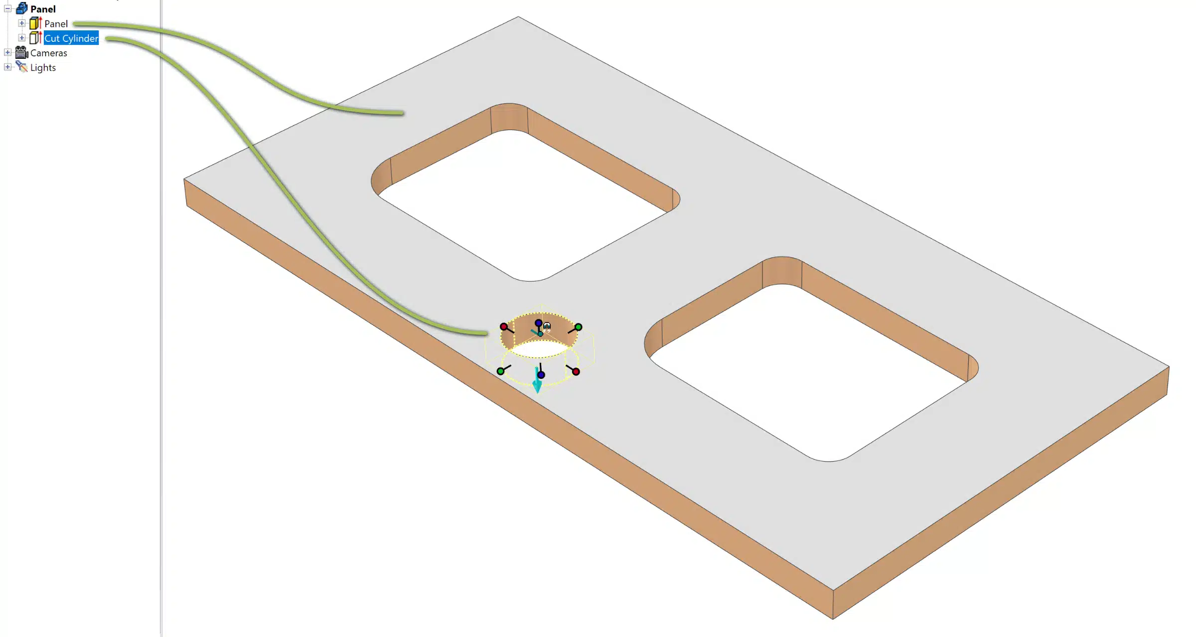
For blind holes, the anchor point ![]() determines whether the tool approaches the cross-section lines from above or below. This is illustrated by the image below and does not apply to through holes; these are corrected in the rule set.
determines whether the tool approaches the cross-section lines from above or below. This is illustrated by the image below and does not apply to through holes; these are corrected in the rule set.
Good to know: the position of the anchor point does not affect the processing of a part.

4 - Determining the top and bottom sides of a panel
![]() By default, the side of the panel with the most operations is treated as the top side. If there are an equal number of operations on the top and bottom sides, the Extrusion Direction Arrow determines the top side. The arrow then points in the direction of the machine bed. If a specific side should be the top, this can be specified via the Panel Manager (accessible via Support Mode, see FAQ).
By default, the side of the panel with the most operations is treated as the top side. If there are an equal number of operations on the top and bottom sides, the Extrusion Direction Arrow determines the top side. The arrow then points in the direction of the machine bed. If a specific side should be the top, this can be specified via the Panel Manager (accessible via Support Mode, see FAQ).
5 - Do not combine drilling and milling operations in one IntelliShape
Drillings and milling operations are handled separately in WoodlabCAM. If they are drawn together in a Cross Section, everything is loaded as a milling operation.
Outer and inner contours, as well as different milling operations, can, however, be drawn together in a single IntelliShape.
6 - Specific milling instructions can be configured using CAD tools
CAD tools are tags that allow you to directly link various properties to IntelliShapes. These can be quickly applied by adding a vertical bar ‘|’ followed by the CAD tool to the element’s name, for example, “Recess |DELETE”. There are a number of general CAD tools, but they can also be custom-programmed. More information on this can be found on this page.
A few examples:
DELETE: For ignoring an operation such as a recess created in the workpiece. The operation remains visible in IronCAD—and thus to the customer—but will not be milled.
CONTOUR: For contouring (line milling) an element which, according to standard rules, will be treated as a recess.
SPLIT: For splitting a milling line into two parts. For example, for a left- and right-rotating milling cutter to avoid damaging edge banding.

7 - Outer contours: rounding or chamfering corners
For outer contours, the Blend ![]() or Chamfer
or Chamfer ![]() functions can be used on the corners. Make sure that the processing for this is enabled in the CAM export options in Para-Flex.
functions can be used on the corners. Make sure that the processing for this is enabled in the CAM export options in Para-Flex.
Using these functions ensures that the standard sides (L1, L2, B1, and B2) remain intact and recognizable to the milling software. If the cross-section lines are adjusted, the CNC stop may end up on a different side.
8 - Inner contours: rounding or chamfering corners
When editing corners in an inner contour, use the Cross Section function and do not use the Blend ![]() or Chamfer
or Chamfer ![]() functions (these are ignored by the CAM software). When using the Cross Section function, be sure to follow the guidelines for fillets, as described below.
functions (these are ignored by the CAM software). When using the Cross Section function, be sure to follow the guidelines for fillets, as described below.
Addition: editing the Cross section
Use of curved shapes
Many CAM software programs (including WoodlabCAM) only recognize curved shapes if they are composed of 3-point arcs. A rounded corner must therefore be drawn as an arc and not using the Fillet function.
Ellipses, B-splines, or Bézier curves for organic shapes should also be avoided to prevent error messages during import.
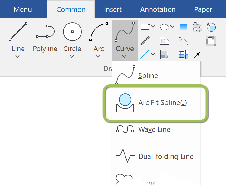
Using IronCAD Draft (previously called Caxa) or similar programs, such curves can be converted into standard circular lines. To do this, use the function shown in the image to the right.
A video showing Arc Fit Spline can be found here. It handles converting an ellipse to spline by creating an offset at 0mm. When a view of this part is created in Draft, the spline is converted to multiple arcs.
Using Chamfers and Fillets
In Cross Section, the use of fillets is not recommended due to potential processing errors by CAM software. To avoid error messages, it is recommended to draw a 3-point arc for such corner adjustments. However, chamfers can be used without any issues.

