
Automatically create cutouts and holes
![]() Pro
Pro
How it works
Drill shapes for creating a cut out should be drawn as an IntelliShape in the part it belongs to.
Use positive IntelliShapes for this function, don’t use the Cut variants that remove material by themselves: use the shapes that ‘add material’ to the model.
These IntelliShapes can be suppressed so they won’t be visible in the model, but still do their job.
Based on these HWDrill shapes, the drill function creates the cut outs in all the parts with which they come into contact

Examples in Para-Flex catalog items
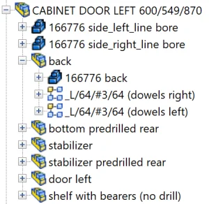
In the Para-Flex sample catalogs many parts contain drill shapes. They can be found when expanding a part (click on the plus sign in front of it). Look for a shape called HWDrill and if desired unsuppress it. The shapes can be edited like every other IntelliShape in IronCAD.
Applying drills to parts
Providing parts with drilling shapes, works easy and intuitive. Often the standard Shapes catalog is used to drag a shape on the relevant Part. This IntelliShape can be repositioned, resized and reshaped as desired. Keep in mind that these shapes are IntelliShapes, so they’ll become a component of the Part they are dropped on.
Also pay attention to the Anchor point of the IntelliShape, for easy CNC automation in the future. The long axis of the anchor has to point in the direction the cutter head will come from when drilling in real live.
![]()
For non CAM users
When you don’t use the CAM capabilities of Para-Flex, it is still a good idea to keep the anchor’s direction in mind. This way, the models created are ready for future upgrades and can be outsourced to companies that do use Para-Flex CAM.
Step by step
In short, the process of creating drilling shapes works as follows:
- Drop a positive IntelliShape on the desired Part.
- Reshape and reposition this item as desired.
- Rename the IntelliShape to ‘HWDrill’.
- Make sure the anchor is pointing in the right direction (towards the cutter head).
- If needed, suppress the IntelliShape to keep your design clean.
Tips
- Recognition of the name/text ‘HWDrill’ by the drill tool isn’t case sensitive.
- The cutting shape should be an intellishape that adds material (though it creates cut outs), so use the positive basic shapes, not the Cut variants.
- If it is desired to have the drilling shapes not visible, simply set the drill shape to Suppress.
Good to know
Recognizing holes
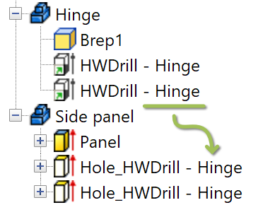
Although the name of a shape to be used for a drill operation has to contain ‘HWDrill’, every text can be added to the expression for easier identification of the result of this drill shape. For example a shape called ‘HWDrill – Hinge’ can be found as cut out shape in a side panel called ‘Hole_HWDrill – Hinge’. That makes it easier to recognize the origin of the cut outs.
Dividing the model into assemblies
We advise to divide models into assemblies for a better overview and faster processing in IronCAD. E.g. when dowels need to be drilled into a panel, put the respective dowels and panel together into one assembly. An additional advantage of grouping them is that the dowels can easily be calculated according to a pattern that relies on the panel size.
The use of smart panels (For Pro/CAM users)
Although this is not necessary for the Drill function to work, we recommend users of Para-Flex Pro and higher to use so called ‘Smart Panels’ for board materials.
Parts based on Smart Panels behave like normal blocks in IronCAD, but are enhanced with additional intelligence. For example, the thickness and textures of Smart Panels can be controlled by Para-Flex, bottom and top sides are recognized, and sides for edge finishing are visually displayed in IronCAD. Compared to standard Parts/IntelliShapes, the Smart panels also offer capabilities for automatic CNC programming, such as CNC reference side and linking predefined milling tools.
Panels used in the catalogs provided by Dynfos are build up from smart panels.
More information for a good CAM workflow can be found here.
The result of the Anchor's orientation
As mentioned above, the direction of the Anchor Point of a HWDrill Shape is important to check (especially for CAM-users). Having mulitiple (blind) drills placed on the same side of a panel, the Anchor Points should point in the exact same direction. The long axis should point in the direction the cutter head comes from. For through holes, the influence of the anchor can often be corrected by the post processor, but when the anchor of a blind hole is pointing in the wrong direction, it depends on the settings in the post processor how this is handled.
![]()
Two examples of what can happen when different Anchor Point directions are combined on one side of a panel:
- The post processor could generate two programs, each for one side of the panel.
- The post processor could add a so called NC-Stop to give the ability to rotate the panel on the machine.
Warning! When the Anchor Point of a blind hole is pointing towards the wrong direction, it is possible the CNC machine cuts out the hole from the wrong side of the panel.
Tips
- After the Drill operation, the shapes are set back to their original suppress state.
- The drilling operation will be slower if there is a mix of ACIS and Parasolid parts in a scene.
Drilling selected items
The window that pops up when clicking the Drill button shows the checkbox to only drill selected items. This can be used when only a selection of the model needs to be drilled, as it speeds up the process. Of course the checkbox is only available when a selection in IronCAD is active.
Take into account that when the checkbox is selected, only the selected items will recieve drills.


